The next steps

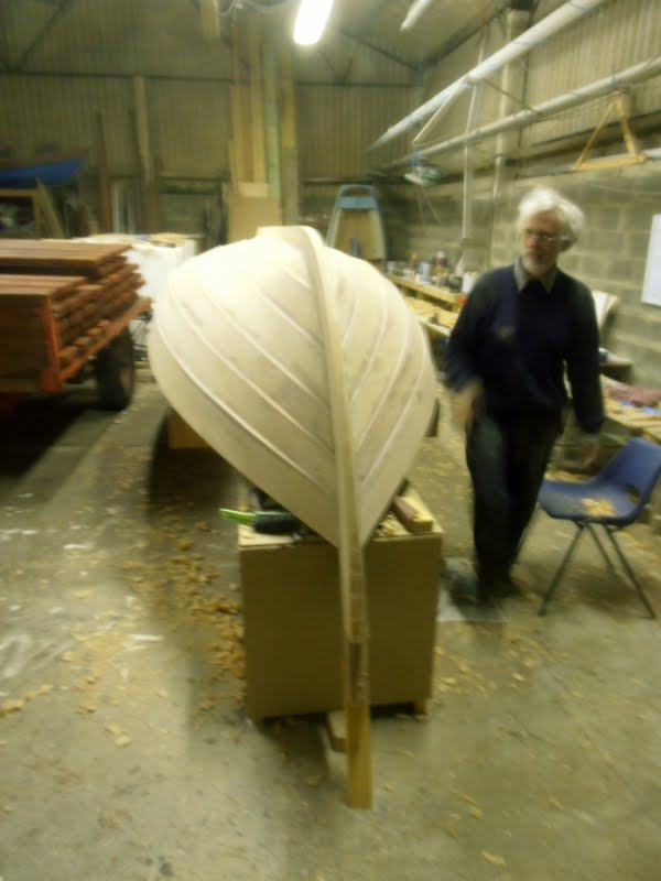
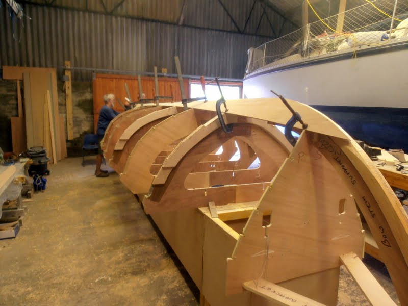
Now that the hull is planked we have to complete the tasks in the last jobs list, which will take some time, so there’s no point in my posting weekly lists of things to be done. The main thing is that the work becomes much more interesting and we hope that Sunday afternoons in the cow shed will become a mini visitor attraction for those wanting to become involved, as well as those who are already interested but have not visited yet.

Remember, it’s absolutely not necessary to buy a share to take part in Seil Coastal Rowing, nor to be resident on Seil (for example I’m not). This is a genuine community project open to all who want to take part and there will be lots to do supporting the skiff as well as rowing her.

Turning to practical matters we have to decide a number of things fairly soon.

Nick Bowles has suggested that a nice colour scheme would involve a cream hull with a slate grey sheerplank and a lighter grey interior. Personally I think this would look great and I love the local reference, apart from which there seem to be no other skiffs sporting grey at present.  It also widens our geographical range to include the other slate islands. Looking at the picture of other boats online it seems that lighter hulls work well with the St Ayles skiff profile. Any other suggestions?

We’ve also been thinking about the extent to which we can make minor deviations (improvements?) on Iain Oughtred’s design, while making sure  that we stay within the Class Rules. The following exchange of emails among Ewan Kennedy, Robbie Wightman and Topher Dawson is relevant.

Ewan’s email to Topher and Robbie

“There are a few practical matters that I’d like to run past you ….

It seems that rudder design is uncontrolled and we are free to plan what we want in terms of the size, shape and angle of incidence of the rudder blade.

It also seems that there’s no problem with an open inwhale, which we see in the photos of other boats and would like to adopt.

We’re considering moving the thwart positions a wee bit forward, as we see that some skiffs are squatting especially when they have a heavy cox aboard. I think some teams have done this already.

Finally I’m thinking of introducing a small amount of rocker, possibly reducing the depth of the external keel at the ends by an inch or so from Iain’s construction drawing. It’s difficult to be sure from the photos online, but it looks as if there are some variations already in keel profile.”

Topher’s Reply

“Well done for getting the planking finished, and I look forward to seeing the finished boat. The rudder does seem to be as you say, uncontrolled, and there are many variations on a theme. Slotted gunwales are also OK and we have gone down that route (without reducing weight) for reasons of strength and drainage.

If you move the thwarts my advice would be to keep the number 3 seat centred on the frame, move the stroke seat 2 inches aft, number 2 seat 2 inches forward and the bow seat 4 inches forward, thus increasing the space for each rower by 2 inches and moving the rowers forward, on average, by an inch. We did this on our second boat and so did the Sailing club here.

Although oars are many and varied, a consensus does seem to be forming that the oars are better restrained in some way from floating in or out at the oarlock. My advice which you are well experienced enough to ignore would be to make the cheap oars on the oar tab of the SCRA website, and then using those as a datum make better ones when you know what you want.

I’d be a bit uneasy about introducing rocker or reducing the outboard part of the keel, because of the advantages to speed and turning which this departure from the plans would introduce. I’m aware as I write this that the same could be said of changing the seat spacing or fiddling with the rudder, but somehow the outside of the hull is sacrosanct, and I would not like to see people cutting their outside keels down to reduce drag. As you say this may already be happening and so far we have not done anything about it, but it could get out of hand.

We may have to issue guidance on this, what do you think, Robbie?”

Robbie’s Reply

“Agree absolutely with Topher.  In the measurement rules there is a difference between hulls and fittings (including thwarts).

For Hulls the rule is:

2.1 The hull is to be constructed as faithfully as possible to the St Ayles Skiff plans produced by Mr Iain Oughtred. The hull may be constructed from a kit from the approved kit supplier or may be built entirely from the plans. That to me excludes varying keel shape by introducing rocker.

For fittings the rule states:

4.1 While the plans show how Rudder, Tiller, Oarlocks, Thwarts, and Seats can be constructed, it is open to the builders to innovate and experiment with these fittings.

4.2 Oarlocks must be at the gunwale. Outriggers are not permitted.

Innovation to me includes spacing the thwarts slightly differently, and that has improved the trim of some boats.  IO introduced extra buoyancy in the hull shape after the prototype to try to sort out the fat cox problem, but the boats do still tend to sit rather heavily by the stern. It can be helped a little bit by the fat cox sitting forward to shout in the stroke’s ear, rather than sitting back and relaxing.

Full measurement rules are here:  http://jordanboats.co.uk/JB/StAyles/Building_Measurement_V5.pdf

We need to form a sub committee to review the measurement rules at some point.”

Clearly there are matters to be decided and it will be helpful for the building team to hear from anyone who has something to contribute to the “variables”.

Jobs List for tonight – 26 September

Sorry it’s a bit late, here is the programme for tonight’s exciting instalment.

Some fairies came along and sorted out the plank gains, so plank 2 is now ready to hang and we’ll get that done tonight. Plank 3 has  been assembled but as it’s rather cold we’d better leave it to cure before clearing the table to assemble plank 4, which already has its scarfs cut.

Plank 2 port side trial fit
Plank 3 glued up

Plank One is on

Another wet Saturday was put to good use, when the first plank sections went on and three of us got a nice masterclass from Richard Pierce, now returned from his adventures in the States.

Our (well, mainly my) efforts at bevelling the keelson and stems to meet the planks were reviewed and mistakes corrected. I had been over-enthusiastic in the sections between the moulds, producing a slight scalloping. It’s quite easy to do this, as one tends to lift the plane when getting near to the moulds and naturally press harder between them. This can’t happen again on Seil Skiff Number One, as there’s only one keelson per hull, but it’s a warning for when we get to our second ship. Fortunately I hadn’t done anything that couldn’t be smoothed out and Richard soon had things sorted.

At the stems I had gone the other way, being afraid of removing too much material. Richard explained how the planks will naturally take a concave curve at the ends, clearly visible in the picture of the finished job. The natural tendency when planing is to concentrate on the sides of the work piece, so that one produces a convex profile and accordingly a bad joint or, worse, an outward lengthwise bow that will produce a bulge in the plank once it’s on, with a compensating flat in the section behind, as the material for the bulge has to be borrowed from somewhere. While one is always anxious not to remove too much it’s actually a lesser sin than not taking enough off. Wood can’t be compressed, whereas an accidental void can always be filled with thickened epoxy. This may be a reason why traditionally-trained craftsmen don’t always look kindly on garage boat-builders – they spend years being trained to produce a perfect fit, then we come along, mix our chemical mud-pies and end up with a stronger boat.

Richard quickly supplied the required concavity with a few passes of one of his favourite tools, the angle-grinder, minus safety guard but with sandpaper on a soft rubber disk replacing the usual wheel. The same tool also cleaned up the edges of the moulds and sorted the angles on the frames.

These corrections done we found that both sections lay sweetly in place, requiring only light hand pressure to come in to the stems, with edges completely fair. It was then a simple matter to glue up the faces and hang both port and starboard sections, securing them with a mixture of temporary screws and clamps. The remaining planks will be progressively easier, the sections having to cope with less and less twist as we move towards the sheer.

angle grinder in use

first plank trial fit

first plank in place
second plank clamped on, photo by RP

Making Our Skiff’s Oars

I’ve been spending a wet Sunday reading the numerous postings by our skiffie friends on their experiences with different types and sizes of oars. They’re very generous in sharing their ideas but this is also quite confusing as it’s clear that there isn’t universal agreement on anything. The purpose of this post is to start a discussion about what we should provide for our first set of oars, bearing in mind that they will be the first of many.

The starting point is the rule book, which outlaws spoon oars and the use of carbon fibre but leaves us free to choose any length, section and shape of blade. It seems that various lengths of oar have been tried and certain lengths lead to clashes more than others. Some impressive work has been done by Topher Dawson suggesting an ideal length of eleven feet, although some teams row successfully with much longer oars. He also recommends rectangular section oars, which are stronger in engineering terms than round ones, although they can’t be feathered. The latter doesn’t seem to bother existing skiffies. Finally he recommends the use of the cheapest whitewood, easily available in a 38mm x 89mm section and adequate length. He’s provided a sketch incorporating these points and I’ve modified it a little, mainly by suggesting the addition of softwood blocks to give a little weight at the inboard end, which I think could be beneficial (some add lead to  thehandles to achieve this). You will see that the 89mm dimension is used fore and aft, where it’s needed. There are thin hardwood strips on three faces to cope with chafe against the kabes.

All comments are welcome but unless anyone comes up with something better I suspect our Wednesday regulars will soon start making our first set to this pattern.

September 5th

Fairing up the frames to take the planks

The frames are now clamped to the moulds and the inner keel piece (sorry – don’t know the right name for  this) has been glued onto them. Now this keel piece has to be bevelled and shaped to take the first plank.  The frames all have to be bevelled by hand to take the curve of each individual plank – a time-consuming process.

Frames clamped to the mould, inner keel piece glued in place

Checking the frames with a dummy plank

A dummy plank is clamped along the frames to check the angle.  This section is looking good.

Checking the bevel on the frames
Checking the bevel on the frames. The inner stem piece is now in place.

Making the first plank

The chief beveller and scarfer decides he has had enough practice and the first plank is ready for assembly. It comes in three sections that have  to be scarfed together with epoxy. In the picture you can see one of the scarf joints clamped and in the background the bevels cut on the second plank.

First plank being assembled

Next – gluing the garboard strake in place

Once the plank is glued we need to painstakingly  finish truing the inner keel piece, the inner stems and the inner bevels on the frames to make sure the plank is a perfect fit. This plank, the one near the keel, is known as the garboard strake. It (and its partner on the other side) will be the most difficult to fit because it has to take the greatest amount of bending.

Gluing the garboard strake is likely to be a Wednesday night job as it will need three or four people. Whether or not it is next Wednesday depends on the progress made in the interim on fairing the keel and stems –  there is a lot of work to be done yet.

After the garboard strakes the rest of the planking should just get easier and easier as we work up (or down!) towards the sheerline. Or at least, that’s what the head boatbuilder says 🙂


Making the Boat at last

Everyone in the team felt good that last night we were beginning to make parts for the actual boat, rather than just clearing and preparing our building space and doing preparations. We also now have behind us our first experience of using the MAS Epoxy resin and for some our first shot at using any version of this magic ingredient. What follows is a description of the process, which I hope will be useful beyond our own Skiff for Seil.

Procedure for laminating stems

The stems on the St Ayles Skiff involve fairly sharp bends and if the decision is taken to laminate them, rather than to cut them from solid timber, the strips must be very flexible.

Seil, in common with most teams, decided to laminate and we sourced some very clear Douglas Fir with a low enough moisture content to glue with epoxy. Most people will be familiar with the basic principles involved, but it may be helpful for us to record some points of detail from the process.

Machining the wood

To do this on a bandsaw would need a massive machine, as small domestic ones are no way up to the task and the blade will simply wander off. Using a commercial table saw gives perfect strips at the cost of quite a bit of wastage through the wider saw cut, but is clearly the way to go.

It’s essential to cut some test strips to prove that the results will take the curve without breaking. Watch the growth rings as you will find that the wood bends more happily along the grain. Our strips are just under 1/4 inch, meaning that we needed about forty to do the two inner and two outer pieces. These turned out just about right, taking the bends without complaint and showing no tendency to spring back once unclamped.

Before starting to cut John our expert thicknessed the planks to 2 3/16ths and trued the edges, to ensure that the finished pieces were uniform. This is worth doing as it greatly neatens the work later.

Mark the pieces, as you will want to reverse every second one, end to end and back to front, to equalise out any stresses in the wood.

The strips laid out for spreading the laminate

Using a scrieve board

The traditional way to laminate a stem is to make a jig from solid timber to go round the inside of the curve and use large clamps to bring the strips in to it. This wastes a lot of time, as more effort goes into the jig than the actual work and only makes sense if several boats are being built.

We have a heavy chipboard base, painted white, on which the curve of the piece can be drawn from the pattern provided. Angle brackets are bolted to this, to which clamps will draw in the glued strips. It’s probably better to have the brackets along the inside, concave face of the pattern, as the clamps will be more effective, although some say this stresses the strips more during the process.

The board and the brackets must be protected from glue. It’s less messy to use plastic sheeting for this, rather than to cover everything with sticky tape, which will need to be removed later.

The scrieve board  bolted together
The scrieve board bolted together

Sorting out the strips

Next the strips are selected, inspected, then double inverted as described above, then numbered and the gluing faces marked, for example A-A, B-B and so on, as it’s terribly easy during the excitement of the process to lose track.

Mark off a couple of inches at one end of each strip (the end that will be nearest to the floor) that will be kept clear of glue so that you can lift them. Also mark the outside faces of the end strips for no glue.

Stack the strips in order and drill a hole for a large nail to keep them in place.

If in any doubt try the whole thing out without glue.

Strips marked for easy assembly once the glue has been spread

Gluing the strips

Set the strips out in order on a level surface covered with plastic sheeting and give them a good drink of neat epoxy, followed by thickened stuff per the makers instructions. Our strips were quite dry and thirsty.

Once they’re all nice and sticky stack the strips on the nail and carry the bundle to the scrieve board.

Clamping up

Start clamping from the nail end, gently bringing the bundle together with a couple of clamps, then adding more as you work along the bundle. Protect the wood from the jaws of the clamps with little wooden pads.

Some strips may want to rise up from the board and must be pressed or battered down with a mallet.

The stem glued and clamped

Clean up

Dispose of surplus plastic sheeting, gloves and any glue spills. Resist the temptation to poke the strips. Just go home and dream about the new stem cresting the waves.

Here's one we made earlier
Here’s one we made earlier

Job List for 8 August

First, last week’s progress.

We got on with trimming the surplus pieces off the mould and frame sections and there’s a lot more of this to be done before we can assemble them on the building base.

Construction of the building base itself was completed.

The brackets were all cleaned up and since Wednesday some progress has been made with laminating the first stem section.

This Wednesday we can:-

Finish the Mould and Frame Pieces

Cut off the webs, smooth the frame sections for assembly.

We should cut the cross-spalls and dry fit everything for later assembly next week once the caterpillar is done.

A minor change of plan – it’s very useful to have the building base on which to laminate the stem sections, so we’ll delay permanent assembly to allow this.

Laminate another stem piece

We’ll check the one that’s been done, reset the brackets and do another.

 Tools and stuff report:-

If you have a Japanese pull-saw or similar please bring it. Having only one causes log-jams.

Don’t forget to collect used plastic tubs and bring them along. We need all we can get.

Some clear light plastic sheeting will be useful, to keep glue off the laminating board.

Job List for 1 August

First, where we’re at just now.

Last week we got most of the jobs on the list done and also found time to chat to the Kilmelford folk.

Construction of the building base went well, with the legs fitting the floor nicely and leaving only the wee two foot box to be done. (The fairies didn’t turn up later to finish it as they’d gone to Jura.)

It’s beginning to look like an mdf caterpillar, which might be its new name.

The 36 plank pieces are pretty well done.

Almost done was the heroic work of cutting out the mould and frame pieces, a much bigger job than anticipated.

This Wednesday we can:-

Complete the Caterpillar

Complete the wee third box, fine tune everything, then glue everything in place.

Finish the Mould and Frame Pieces

Cut off the webs, smooth the frame sections for assembly.

Cut the cross-spalls, dry fit everything for assembly next week once the caterpillar is done.

Prepare the Laminating Board and Brackets

The stem patterns need to be marked onto the board, then the stiffening pieces screwed to the back.

The brackets need to be cleaned of old tape and epoxy, then positioned and bolted to the base

Tools and stuff report:-

We now have a good supply of sandpaper, parcel tape for protecting edges from glue and a set of digital scales.